Vanguard Medium FTS 370 Updated for 43J Compliance Tech Bulletin
Flash Technology is issuing this technical bulletin to notify customers, sales, technical support and service teams of the changes made to the Vanguard FTS 370 as a result of the new FAA AC 150/5345-43J.
To comply with the AC, Flash Technology has made the following changes to the product:
- Redesigned the FH 370 core board
- Released a new marker, MKR 372 (L-810)
- Implemented use of a 3-conductor shielded cable with markers
- Released a new Marker Interface Board
- Released Marker Firmware V3.0 to support these changes
The changes have been implemented effective September 4, 2020.
Background
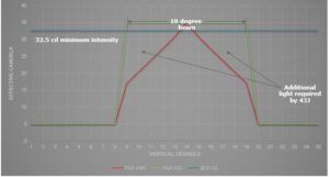
The FAA released AC 150/5345-43J which affects all towers filed after September 11, 2020. Apart from specifying the addition of IR emitters to help visibility with NVG/NVIS, the FAA also made changes to the beam profile of L-810 markers and mandated the ability to detect 25% failure in both red and IR emitters.
These FAA changes necessitated the following changes in the Vanguard Medium FTS 370x obstruction lighting system:
- New core board in flashhead to accommodate IR LED
- A new MKR 372 marker that fits the FAA specified beam profile
- A 3-conductor marker cable to work with the new markers
- A new Marker Interface Board that controls the new markers
- Firmware that controls operation and performance monitoring of the new Marker Interface Board.
FLASHHEAD CORE BOARD
- F2422600T PCB CORE BOARD FH 370D/W IR TESTED
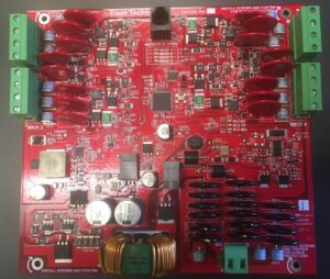
Flash Technology has redesigned the flashhead core board to support the addition of IR LED into the flashhead. The new core board is colored red to easily differentiate it from the previous version (F2422500T colored black) and all new systems are equipped with the red board.
When replacing a core board in the field for any reason, follow these guidelines:
- When replacing core boards, always swap ‘like for like’. For example, swap red board for red board or black for black.
- NEVER replace a red core board with a black core board. It will damage the IR LEDs in the flashhead and void the warranty.
- Failure of IR LED cannot be detected by the naked eye
- Failure may not be immediately apparent
- Do not replace a black core board with a red core board.
- The LED strings will not be connected correctly and consequently, the light intensity may be lower than the FAA specified minimums.
- Monitoring operations will not be able to identify IR capability of the flashhead.
- Improper connections may result in some white LEDs being activated in red night mode. This is a danger to pilots and violates the FAA directive against both red and white lights being energized at the same time.
NOTE: Only flashheads with red core boards are in compliance with AC 150/5345-43J and AC 70/7460-1M.
MKR 372
- F1901110 MARKER KIT 1-MKR 372 DC L810 FAA
- F1901120 MARKER KIT 2-MKR 372 DC L810 FAA
- F1901130 MARKER KIT 3-MKR 372 DC L810 FAA
- F1901140 MARKER KIT 4-MKR 372 DC L810 FAA
- F1904205 MKR 372 DC L810 FAA IR OL2
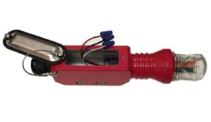
The new MKR 372 is certified as being in compliance with AC 150/5345-43J and is listed in the Airport Lighting Equipment Certification Program (ALECP) addendum published by the FAA. The marker contains both red LED emitters and IR LED emitters. It replaces MKR 371 in all FAA jurisdictions.
Externally, MKR 372 is identical to MKR 371. It has the same form factor and the same number of conductors.
MKR 372 incorporates the third, “SENSE wire” conductor in its operation to determine if the red and/or the IR LEDs are working as mandated by the FAA.
The incorporation of the SENSE wire has required a change in the marker cable used for the application (See MARKER CABLE section below).
Instructions on wiring the new markers are detailed in a Quick Start Guide (F7904214 MKR 372 & MKR 371 QSG REV3) which will ship with each marker.
MARKER CABLE
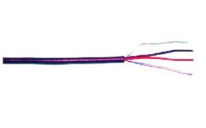
- F4319000 CABLE TC RATED 18AWG/3C MKR 371 / MKR 372
3 Conductor + Drain Wire Cable
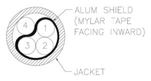
Conductor #
1
2
3
4
Color
Black
Red
White/Blue
Drain
Figure 4: Cable Cross-Section
The mandate from the FAA to be able to detect a 25% failure in either red or IR LED necessitated a change in the type of marker cable used by the FTS 370 systems.
Cable F4319000 CABLE TC RATED 18AWG/3C MKR 371, is a cable containing 3 conductors and a drain wire. It replaces the previous cable (F4318000) which used 2 conductors and a drain wire. All existing kit part numbers have been updated to include the new cable.
While new to the FTS 370 product line, this cable has been in operation with Flash Technology’s FTS 371 product line for several years and has proved its capability and longevity in the field.
MARKER INTERFACE BOARD
F2422200T PCB MARKER JBOX DC FTS 370D MKR 372 TEST
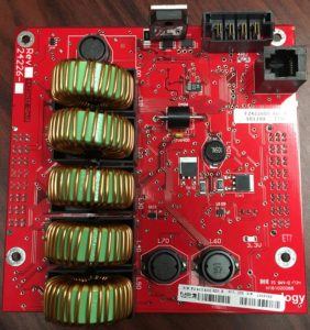
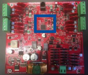
A new Marker Interface Board has been released in conjunction with the release of MKR 372. This new board replaces the previous version (F2422000T). There are several changes of note:
- The board is colored red to differentiate it from the old board which was black.
- It uses 4 pin connectors for each marker (DC+, DC-, Sense snd Shield). The previous board used 3 pin connectors.
- The board is backward compatible. It will fit into the existing Marker Interface Box and can be used with previously installed MKR 371 markers.
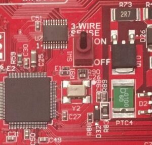
- Each marker interface board is equipped with a “3-WIRE SENSE” selector switch (see figure 6 below) to enable use with either MKR 371 or MKR 372.
- When used with MKR 372, the switch must be placed in the “ON” (up) position to ensure 43J compliance.
- When used with one or more MKR 371, the switch must be placed in the “OFF” (down) positon.
- The Marker Interface Board is also compatible with other legacy L-810 markers supplied by Flash Technology. The 3-WIRE SENSE switch will be toggled to the “OFF” position when using these markers.
Figure 7: Selector Switch and location on marker interface board
Note: Incorrect positioning of the switch will result in a Marker Alarm.
Detailed instructions to install the Marker Interface Board in each configuration is detailed in a Quick Start Guide (F7904208 VANGUARD DC MKR JBOX) which ships with the product. A Trouble Shooting Guide “TSG Marker Interface Board F2422200 and MKR 372 Installs” is also available to facilitate trouble-free installs.
FIRMWARE
F2422200 – FTS370d MKR372 DC Int FW V3.0
FW V3.0 and above is written for the new Marker Interface Board (F2422200) and enables AC 150/5345- 43J compliance. The FW adds the following functionality:
- Enables detection of individual markers in the tier. Previously control was by tier rather than individual markers.
- Turns off individual markers if 25% of either RED or IR LED have failed as mandated by FAA
- Enables backward compatibility with legacy L-810 markers with appropriate toggle setting of the 3- WIRE SENSE switch (“OFF” positon).
The firmware is preloaded into the Marker Interface Board.
RELATED DOCUMENTS
- FAA AC 70/7460-1M
- FAA AC 150/5345-43J
- FAA AC 150/5345-53D
- QSG: F7904214 MKR 372 & MKR 371 QSG REV3
- QSG: F7904208 VANGUARD DC MKR JBOX
- TSG: Marker Interface Board F2422200 and MKR 372 Installs
Please contact Tech Support if you have any issues at 800.821.5825, option 9
- Monday–Friday, 7am–7pm US Central Time

