- Equipment
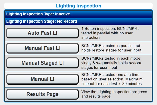
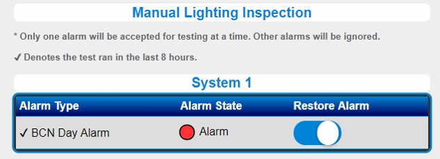
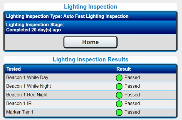
- Lighting Inspections
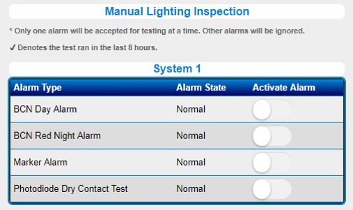
- Mode Override
- Beacon Status
- Marker Status
- Controller Status
- Diagnostics and Configuration
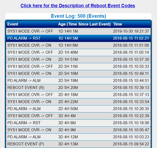
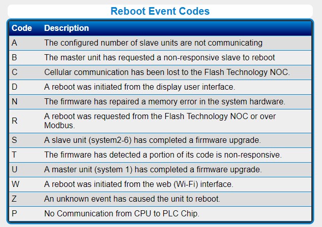
- Event Log
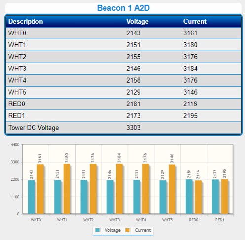
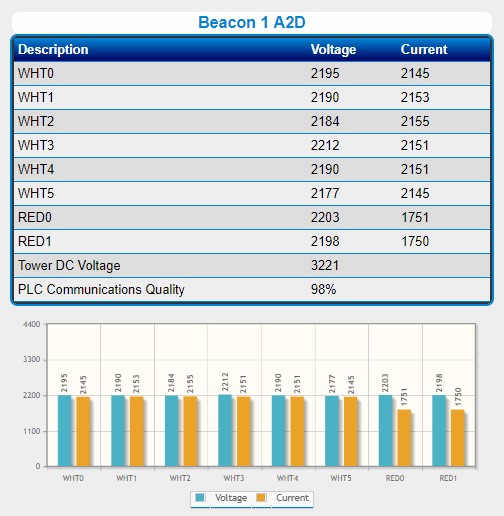
- Beacon Diagnostics
- Marker Diagnostics
Home Page:
- Gives option to enter desired site name and ID
- Identify the exact site under discussion when accessing multiple sites at once.
- Product Manual Link (No internet required)
- Flash Technology support phone number
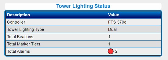
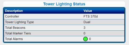
Tower Lighting Status:
- Exact lighting equipment on tower
- Number of Beacons and Marker Tiers
- Total Alarms (active)
Mode Override:
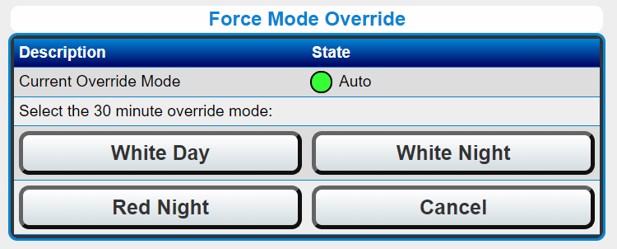
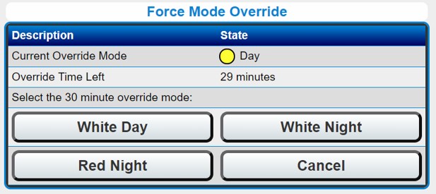
- Mode change command triggers a 30 min override
- Ability to cancel an existing mode override
- Displays current override mode
- Displays time remaining in minutes for the current mode override
- Longer than 30 min overrides can be initiated remotely through Modbus or SNMP for up to 45 days.
V3.6+: Mode Overrides remembered between power cycles
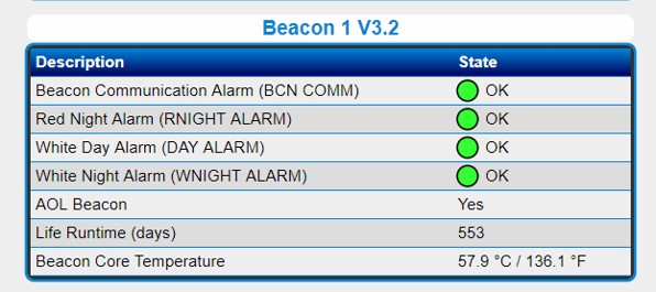
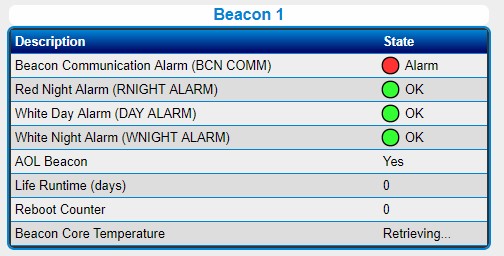
Beacon Status:
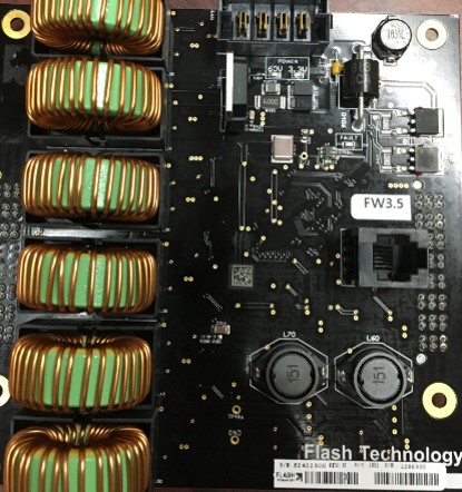
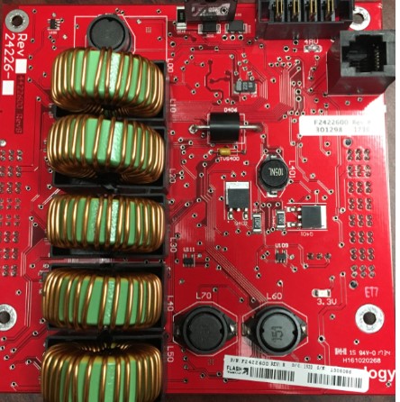
- Displays Beacon # (position) & Firmware (FW) Version
- If V1.2 – V1.6 = IR
- If V2.3 and up = Non-IR
- Status of individual alarms – OK / ALARM
- AOL Beacon selection
- Total Runtime (in days)
- Beacon “Core” Temperature
- If alarm(s) present, check the diagnostics page
- If COMM Alarm is active, check the following:
- Is Power Failure Alarm active?
- Is Low DC Alarm active?
- Check DIAG for Input voltage A2D values
See COMM alarm troubleshooting for additional information.
Core Board Types Are Not Interchangeable
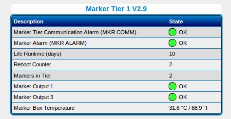
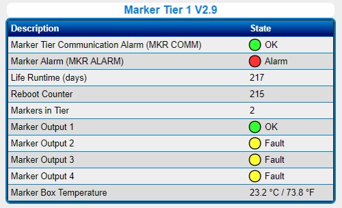
Marker Status:
- Displays Marker Tier # and FW Version
- # of markers configured in a tier
- Status of marker alarms OK / ALARM
- Individual marker status OK / Fault
- Note: If markers are not connected, a Fault is indicated.
- Total runtime in days since first power-up
- Marker Box Temperature (board)
- If there is a marker alarm, check “Markers in Tier” to verify MKR condition (OK / Fault)
- If COMM Alarm is active, check the following:
- Is Power Failure Alarm active?
- Is Low DC Alarm active?
- Check DIAG for Input voltage A2D value
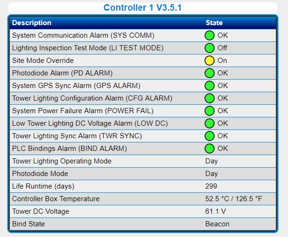
Controller (PCB1) Status:
- Displays Controller # and FW Version
- Status of individual alarms OK / ALARM
- Tower lighting operating and PHD modes
- Under normal conditions both should be same
- Total runtime in days
- Controller Box Temperature
- Tower Bind Status – Shows the devices it is bound to.
- If COMM Alarm is active, check the following:
- Is Power Failure Alarm active?
- Is Low DC Alarm active?
- Check DIAG for Input voltage A2D values
See COMM alarm troubleshooting for additional information.
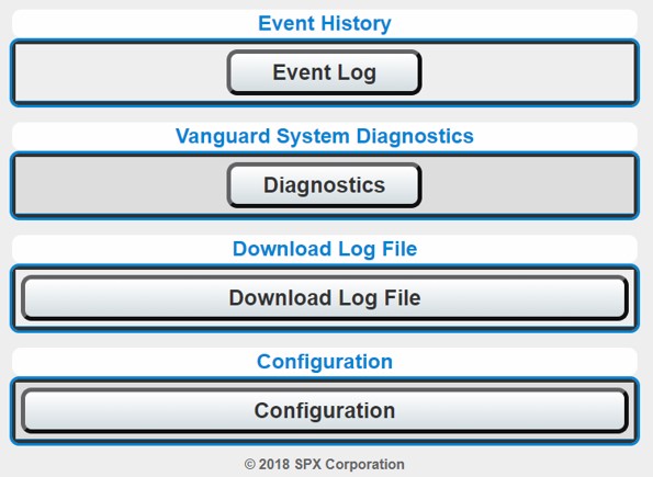
Diagnostics And Configuration Options:
- Event Log lists the last 500 events in descending order (most recent first with uptime since last power up)
- System diagnostics provides the diagnostics for each device, including A2D values
- Download Log File (V3.5+) to obtain the log data for the last 2 days
- Send file to Flash Technology for manufacturer troubleshooting
- Configuration:
- Multiple device configurations can be set
- By default, no password to access system
- User can enable multiple levels of password protection to restrict access to the config page, mode override and LI commands
- Changes are made in the Login Settings page
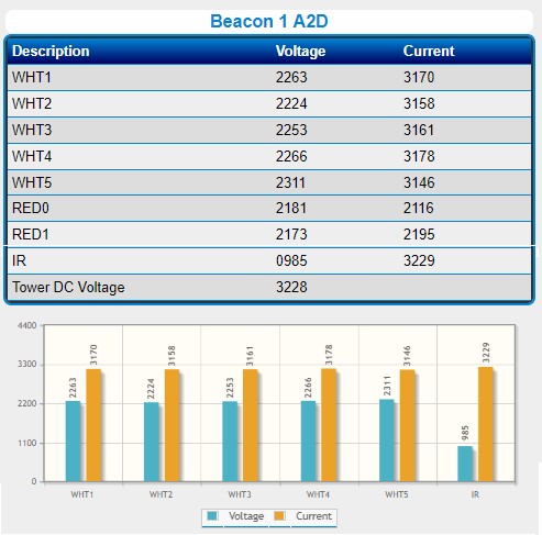
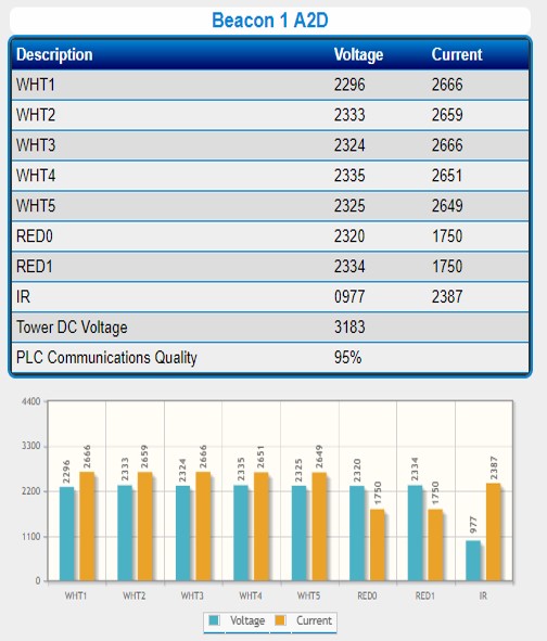
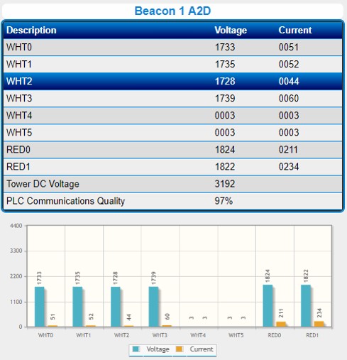
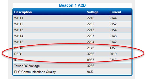
Beacon# A2D Lighting Alarms:
- Recommend replacing the surge board with any flashhead core board replacement.
- Replace Flashhead if:
- Voltage is high and current is low (Failed open)
- Voltage is low but current is normal (Failed short)
- Replace Core Board if:
- Voltage High and current High
- Voltage High and current Normal
- Voltage Normal and current High or Low
- Voltage Low and current High
- Voltage Low and current Low
Diagnostics Page: Marker# A2D in ALARM
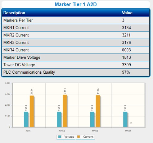
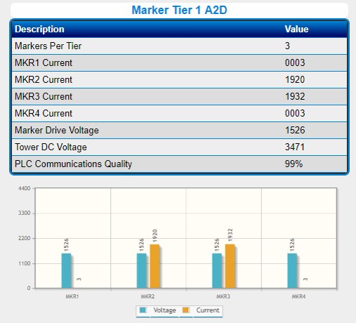
- A2D values for each marker output
- Marker Drive Voltage that powers each marker
- Tower DC Voltage Nominal Range: ~3400 (58VDC)
- Bar graph of Voltage and Current A2D for MKR
- Only 2 current values for 3 markers in the graphic indicate that (1) marker has failed
- Replace Marker if:
- A2D for that marker position is low
- Reporting just marker alarm
- Replace Marker Board if:
- All marker outputs in alarm and Marker Drive Voltage is 0 (zero)
- Check MKR Connections at PCB if Marker Alarm is chattering


